phtumshk
Super Member
    
Joined:May 2014
Posts: 3,758 
Location:
Likes: 4,058
Recent Posts
Last Online Nov 15, 2024 13:54:05 GMT
|
Post by phtumshk on May 10, 2015 1:20:28 GMT
Seemed like a good Idea at the time. i stick stylee 20w board for £6 at FT and an old empty hana case, what could possibly go wrong. up/down buttons were a doddle to remote to the hana switches all wires soldered nicely to the back of the board. Fire button was a little trickier, had to solder wires directly to the on board switch connections. Excuse the hot glue mess Im a lazy sod.  Originally planed to use a separate charge board but heres where the plans went awry. I couldnt get the board to wake up with out first being plugged in to the on board USB port. Bit of a shit when I didnt want to use it so it left me no other option than to drill a big hole in the bottom of the case for the USB cable. Need to fab some kind of rubber grommet to hide the board and stop some of the dirt ingress. 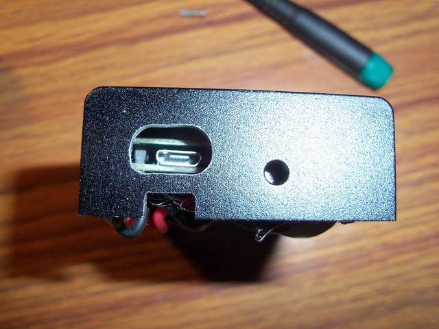 So if you plan on using 1 of these boards in a self build be aware of the need for access to the on board usb  All working nicely, I couldnt get the display any higher because of the 510/buttons but its just about in the oval. 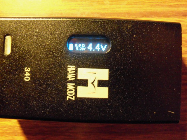 Any 1 interested in the connections on the board to remote switch heres a rough guide to how I did it. NB. I take no responsibility if you attempt this, you do so at your own risk. 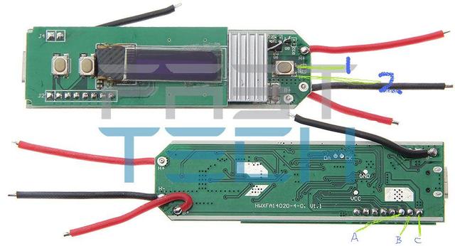 1:Fire button Pos. 2:Fire button Neg. (after soldering these wires on I checked they worked then epoxyed them to the board as the connections were a little fragile) A:Up Button Pos. B:Down Button Pos. C:Common wire for both UP/Down buttons Neg. |
|
Get Off My Cloud
Super Member
     Master of Hardware
Formerly dr00g
Joined:December 2014
Posts: 5,693 
Location:
Likes: 7,691
Recent Posts
Last Online Jan 8, 2021 22:17:08 GMT
|
Post by Get Off My Cloud on May 10, 2015 1:52:08 GMT
Bit of a bugger about the USB, i have a couple of these boards so the diagram is useful especially to a know nothing about wiring plum like me thanks  Question does the board only need waking up the once, can i just wake the board up then install it and not bother with a USB port at all just charge my batteries seperately or does it need waking up each time a battery is installed? |
|
VapingBad
Mod Maker
Mr Fix-it
Joined:January 2014
Posts: 13,800 
Location:
Likes: 14,176
Recent Posts
Last Online Oct 6, 2024 16:13:51 GMT
|
Post by VapingBad on May 10, 2015 1:58:20 GMT
Well done phtumshk get some Sugru (B&Q & maplin Stock it, cheaper on eBay) for the rubber seal you want. For next build you could get a USB socket and just extend the power wired to the PCB and mount it wherever suites.  |
|
phtumshk
Super Member
    
Joined:May 2014
Posts: 3,758 
Location:
Likes: 4,058
Recent Posts
Last Online Nov 15, 2024 13:54:05 GMT
|
Post by phtumshk on May 10, 2015 2:14:09 GMT
Bit of a bugger about the USB, i have a couple of these boards so the diagram is useful especially to a know nothing about wiring plum like me thanks  Question does the board only need waking up the once, can i just wake the board up then install it and not bother with a USB port at all just charge my batteries seperately or does it need waking up each time a battery is installed? I thought it was DOA when I first tried it. Plugged the usb into it and it sprang into life. Every time you take the battery out of the holder and put it back in you need to jump start it with the usb, obviuosly not a problem with the isticks and the wired battery. I was hoping to trace the connections to the POS/NEG of the usb and see if it could be wired to the battery via a momentary switch and give it a quick pulse to wake it up but its a double layered board and I couldnt find them. |
|
phtumshk
Super Member
    
Joined:May 2014
Posts: 3,758 
Location:
Likes: 4,058
Recent Posts
Last Online Nov 15, 2024 13:54:05 GMT
|
Post by phtumshk on May 10, 2015 2:21:11 GMT
Well done phtumshk get some Sugru (B&Q & maplin Stock it, cheaper on eBay) for the rubber seal you want. For next build you could get a USB socket and just extend the power wired to the PCB and mount it wherever suites.  I follow your lead, thats what I was thinking sugru.  Before the DNA went tits up I had a seperate charge board wired to the battery, thats what the other little square hole is for above the big oval 1, was hoping to reuse it. |
|
osdset
Senior Member
   
Joined:May 2014
Posts: 328 
Location:
Likes: 257
Recent Posts
Last Online Mar 6, 2022 6:44:47 GMT
|
Post by osdset on May 10, 2015 6:45:51 GMT
Well done phtumshk get some Sugru (B&Q & maplin Stock it, cheaper on eBay) for the rubber seal you want. For next build you could get a USB socket and just extend the power wired to the PCB and mount it wherever suites.  For a much cheaper alternative to Sugru, make yer own! It's called Oogoo, and it's made from clear silicone sealant mixed with cornstarch, instructions hereFacepalm time! I've just realised after Googling for cornstarch, that it's what the Yanks call cornflour. Huge box in the cupboard and a few tubes of silicone in the shed, it's experiment time! |
|
bigd
Senior Member
    Always watching.
Joined:December 2014
Posts: 447 
Location:
Likes: 228
Recent Posts
Last Online Apr 22, 2019 17:57:55 GMT
|
Post by bigd on May 10, 2015 9:04:58 GMT
Well done phtumshk get some Sugru (B&Q & maplin Stock it, cheaper on eBay) for the rubber seal you want. For next build you could get a USB socket and just extend the power wired to the PCB and mount it wherever suites.  For a much cheaper alternative to Sugru, make yer own! It's called Oogoo, and it's made from clear silicone sealant mixed with cornstarch, instructions hereI've never used any of these products, never even heard them before. But Oogoo looks so impressive I'm gonna buy the ingredients just so I can have a play with some. I'll find a use no doubt one day. |
|
bigd
Senior Member
    Always watching.
Joined:December 2014
Posts: 447 
Location:
Likes: 228
Recent Posts
Last Online Apr 22, 2019 17:57:55 GMT
|
Post by bigd on May 10, 2015 9:05:48 GMT
Keep us to date on that chip please I've ordered a couple to play with.
just a second thought, can the micro USB connector for charging be taken off the board and mounted elsewhere, just extending the wires. Or is not a simple as that. I'm not a sparky obviously, it's just an idea.
|
|
igual
Super Member
     Guide Maker
Joined:July 2014
Posts: 3,402 
Location:
Likes: 2,874
Recent Posts
Last Online Jun 26, 2017 16:25:16 GMT
|
Post by igual on May 10, 2015 9:40:31 GMT
Great nob many thanks for sharing bud.
Would !love to have a go but am still confused as to what wire goes where on these lol.
Mechs are so much simpler ....
|
|
VapingBad
Mod Maker
Mr Fix-it
Joined:January 2014
Posts: 13,800 
Location:
Likes: 14,176
Recent Posts
Last Online Oct 6, 2024 16:13:51 GMT
|
Post by VapingBad on May 10, 2015 10:12:28 GMT
Sugru is easier to work with than oogoo and stays stuck to metal far better, oogoo is good for larger things especially mouldings. Oogoo is so cheap it is worth making some up to have a play with it messy and smelly though. Oogoo mod stand and rubber bands to block air inlets on atties 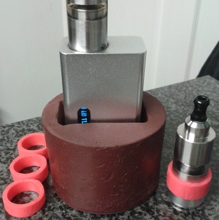 Sugru used in a mod (black stuff) 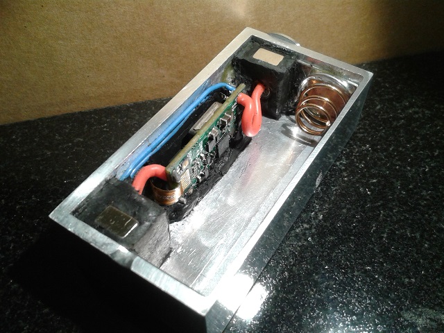 |
|
phtumshk
Super Member
    
Joined:May 2014
Posts: 3,758 
Location:
Likes: 4,058
Recent Posts
Last Online Nov 15, 2024 13:54:05 GMT
|
Post by phtumshk on May 10, 2015 10:48:04 GMT
Keep us to date on that chip please I've ordered a couple to play with. just a second thought, can the micro USB connector for charging be taken off the board and mounted elsewhere, just extending the wires. Or is not a simple as that. I'm not a sparky obviously, it's just an idea. It did cross my mind but with it being a double layer the on board usb is situated in between the 2 boards so its going to be tricky to get at. Having thought about it I think the way round this for me is to remove the plastic moulding from a micro usb cable so you just have the metal bit and the fine wires then just extend from there if that makes sense. Thats what I going to try with the next 1. |
|
bigd
Senior Member
    Always watching.
Joined:December 2014
Posts: 447 
Location:
Likes: 228
Recent Posts
Last Online Apr 22, 2019 17:57:55 GMT
|
Post by bigd on May 10, 2015 13:53:24 GMT
Keep us to date on that chip please I've ordered a couple to play with. just a second thought, can the micro USB connector for charging be taken off the board and mounted elsewhere, just extending the wires. Or is not a simple as that. I'm not a sparky obviously, it's just an idea. It did cross my mind but with it being a double layer the on board usb is situated in between the 2 boards so its going to be tricky to get at. Having thought about it I think the way round this for me is to remove the plastic moulding from a micro usb cable so you just have the metal bit and the fine wires then just extend from there if that makes sense. Thats what I going to try with the next 1. I see what you mean double layer board now on second look. What about cutting one off the boards if you can't see any connection on it so you can get in more. Or, it looks like it's soldered in would desoldering them 2 spots help. just a couple of thoughts, your more experienced than me and have it in your hands. Keep the news coming though. |
|
phtumshk
Super Member
    
Joined:May 2014
Posts: 3,758 
Location:
Likes: 4,058
Recent Posts
Last Online Nov 15, 2024 13:54:05 GMT
|
Post by phtumshk on May 10, 2015 14:37:56 GMT
It did cross my mind but with it being a double layer the on board usb is situated in between the 2 boards so its going to be tricky to get at. Having thought about it I think the way round this for me is to remove the plastic moulding from a micro usb cable so you just have the metal bit and the fine wires then just extend from there if that makes sense. Thats what I going to try with the next 1. I see what you mean double layer board now on second look. What about cutting one off the boards if you can't see any connection on it so you can get in more. Or, it looks like it's soldered in would desoldering them 2 spots help. just a couple of thoughts, your more experienced than me and have it in your hands. Keep the news coming though. If you look on the FT pic to the left hand side of the board where it say J1 & J2 those soldered points are where the 2 pcbs are held together. If I can get hold of a dead 1 Id probably desolder it and have a better look. Im really hoping to sort a solution out as Id like to get hold of a 30w board from an istick or similar and put it in that wooden box i made. |
|